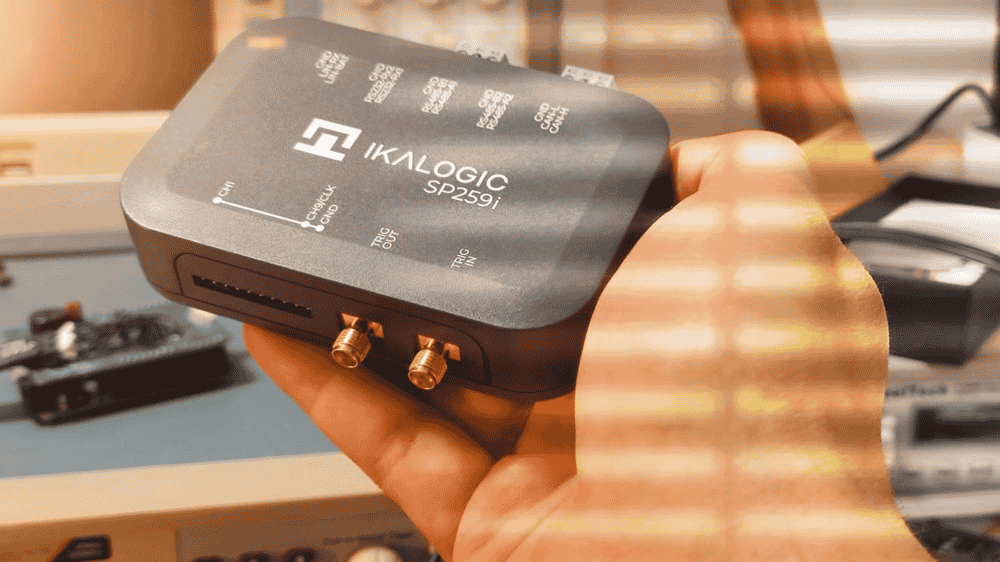
Master RS485 Debugging with the SP259i

Debugging electronics can be a bit of a puzzle, but the SP259i logic analyzer is here to make the process smoother. In this article, we’ll walk through how to use the SP259i to analyze RS485 systems like a pro.
Learn more about SP259iIntroduction
RS485 operates like a group conversation — multiple devices can join, but only one can transmit data at any given moment! It’s designed for robustness and long-distance communication, making it a go-to in industrial automation and building control systems. But, because it relies on differential signals, troubleshooting RS485 can be bit more complex than simple UART (single ended logic levels).
For the purpose of this article, we built a simple test setup with two USB to RS84 converters and an SP259i device in the middle to spy on the bus.
We hope to be able to cause bus congestion, collisions, and demonstrate the usage of the SP259i in this kind of situations.

For the software, we used our all time favorite Teraterm to generate some serial data on both ends of the RS485 network.
In case you don't already know, RS485 is just the physical layer that, in essence, transfers serial UART bytes. That's why later in this article, we'll be using a UART decoder to look at the actual bits and bytes being transferred.
Common RS485 Troubleshooting Challenges
RS485 communication is wonderfully reliable, but not immune to issues. From bus collisions and noise to incorrect terminations and timing mismatches, there are plenty of opportunities for things to go sideways. That’s why a tool like the SP259i is invaluable, as it lets you peek behind the curtain and see exactly what’s happening on the bus. (and by the way, at the time of writing this article, it's the only USB based logic analyzer that has integrated RS485 transceivers).
Setting Up the SP259i for RS485 Analysis
Hardware Setup
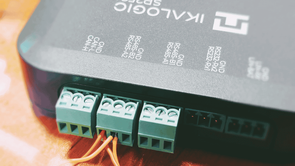
Start by connecting the SP259i to your RS485 bus. Attach its input channels to the A and B lines of the bus, and don’t forget to ground the device—because floating signals are just asking for trouble. An exception to this is when you're sure all devices share the same ground (which is the case in our test setup).
Configuring ScanaStudio and SP259i
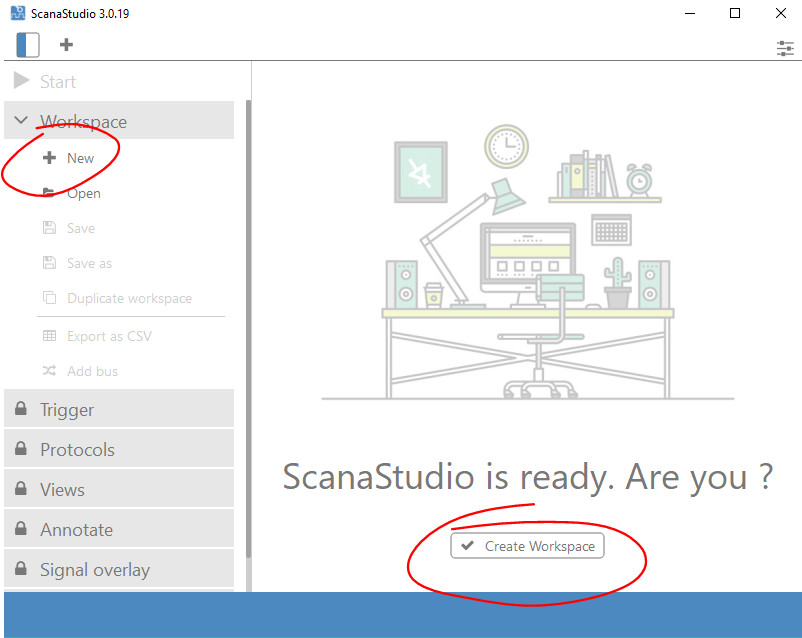
Next, fire up the latest version of ScanaStudio software, and create a new workspace:
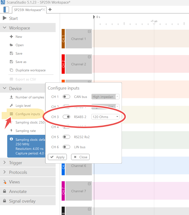
Then, configure the SP259i Logic Analyzer device to use the integrated RS485, and don't forget to chose "120 Ohms" termination if your circuit don't already have one:
Finally, setup a trigger. At this point, the most universal trigger option I like to use is "Trigger on any logic change". This is usually the way to go for a very first logic signals capture:
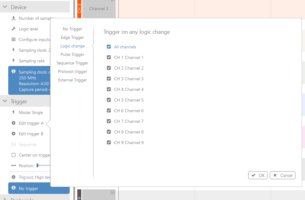
Go ahead and click "Start" and if you send some ASCII characters on the RS485 bus, you should get a trigger, and see signals like this:

Add a serial UART decoder
Now, the most logical thing to do next (whatever is it you're trying to debug in your RS485) is to add a serial UART protocol decoder. To do that, open the protocols tab and :
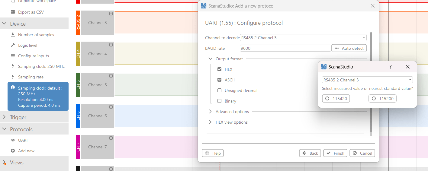
- Click "Add new" and search for UART from the list of supported decoders
- Select the right channel (in our case, it's channel 3, which is multiplexed with RS485 2)
- Set the right baud rate (using the auto detect feature)
- Select the right channel for baud rate detection
Then simply click "Finish" and voila, you should your data decoded as in the image below:

Of course, your RS485 bus might be running at a different baud rate. you'll need to adjust the baud rate (or auto-detect it) in consequence.
If you've made is so far, you already have the knowledge needed to debug and diagnose more than 80% of your RS485 bus troubles. In the next part of the article, we'll focus on less rare cases of RS485 failures.
Debugging Real-Live RS485 bus congestion
For the sake of this article, i wanted to create the most common RS485 bus failure one can encounter: having two master transmitting at the same time (that's why i have two computers attached to the bus in my original test test up). My idea is to have each computer transmit a burst of several hundred bytes, at the same time and hope for a collision (kinda like the Large Hadron Collider, lol!).
Then, I wanted to use advanced trigger features of the SP259i to detect that collision. Spoiler alter: It worked from the first time!
So here is how it goes: i supposed that two masters fighting each others to drive the RS485 bus at the same time would for sure create glitches, glitches that are not in the "normal" timings of the 115200 baud that we're using. We know that 115200 baud results in bit times of approx 8.5 us. So anything smaller than 7 us is abnormal and may be caused by a bus collision.
To try this, setup a "pulse" trigger, and configure the right channel, the right channel polarity and tick only the "Maximum pulse width" with a 7 us maximum timing:
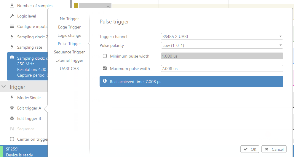
What does this means? Well, in other words, this directs SP259i to trigger on any pulse that is - at most - 7 us long. But any pulse shorter than than (even a 50 ns glitch) will cause the device to trigger.
To test this, we simultaneously send big loads of data from the two computers and wait for a trigger to occur, which didn't take long:

As you can see a trigger occurred at the red marker, now let's zoom in to see if there is a glitch:

And here it is! a 20 ns glitch!
Wrapping It Up
RS485 debugging doesn’t have to feel like a guessing game. With the SP259i logic analyzer, you get a window into your system’s communication, making it easier to identify and resolve issues. Whether it’s noisy signals or timing errors, this tool is a trusty companion for RS485 analysis.
Learn more about SP259iSome Tips for the road (for Accurate RS485 Analysis)
- Use Proper Termination: Termination resistors are your best friends for signal integrity—don’t overlook them. Furthermore, SP259i device offer an integrated 120 Ohm termination resistor that can be enabled with a click of a mouse.
- Ensure ground is properly connected: Ground helps keeping both ends of the RS485 bus a close common voltage level, which is good.
- Leverage Triggering: Custom triggers help you filter out noise and focus on what matters.