End-of-line functional test
This is the test that runs on every board before it ships. One AT1032S takes the place of the bench supply, the multimeter, the logic probe and the pass/fail lamp: it powers the board, measures its rails, exercises one logic path, and shows the verdict on its own screen and speaker. The operator never touches a PC.
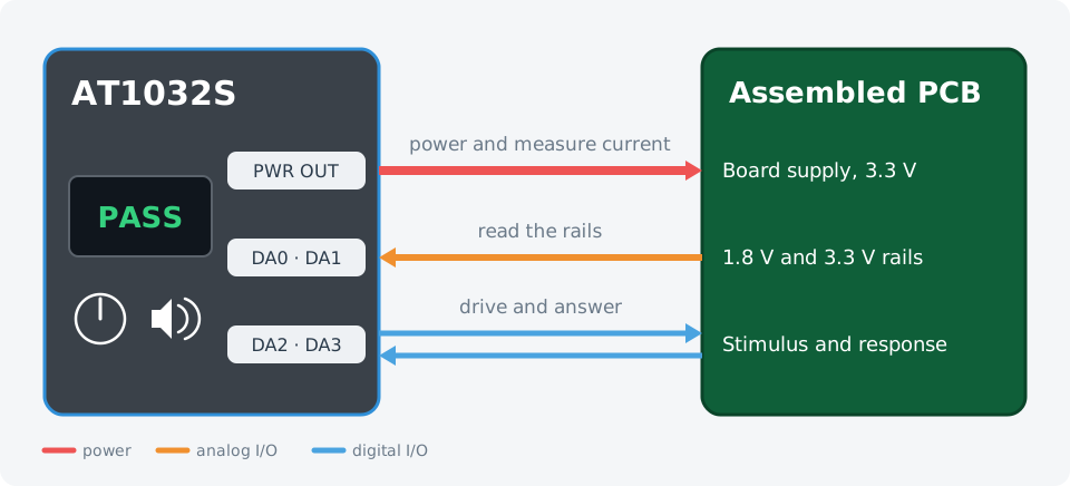
Power, measure, stimulate, read back, report. One instrument, one cable loom.
Wiring
| AT1032S | Device under test |
|---|---|
PWR OUT + / − | Board supply input |
DA0 | 1.8 V rail test point |
DA1 | 3.3 V rail test point |
DA2 | Stimulus input |
DA3 | Response output |
The test sequence
- NodeJS
- Python
import { AT1000 } from '@ikalogic/at1000';

// ---- Everything you adapt for your own board lives here -------------------
const SUPPLY_V = 3.3;          // board supply voltage
const CURRENT_MAX_A = 0.35;    // above this, the board is faulty
const RAILS = [
  { io: 0, name: '1.8 V rail', min: 1.70, max: 1.90 },
  { io: 1, name: '3.3 V rail', min: 3.15, max: 3.45 },
];
const STIMULUS_IO = 2;
const RESPONSE_IO = 3;
const SETTLE_MS = 200;
// ---------------------------------------------------------------------------

const sleep = (ms) => new Promise((resolve) => setTimeout(resolve, ms));

const devices = await AT1000.findDevices();
if (devices.length === 0) {
  console.log('No AT1000 device found.');
  process.exit(1);
}

const tester = await AT1000.open(devices[0]);
await tester.reset();

const supply = tester.power.dut(0);
const stimulus = tester.gpio.digital(STIMULUS_IO);
const response = tester.gpio.digital(RESPONSE_IO);
const screen = tester.hmi.screen();
const speaker = tester.hmi.audio();
const knob = tester.hmi.knob();

await stimulus.configure_output({
  voh: SUPPLY_V, vol: 0, vih: 2.0, vil: 0.8, value: false,
});
await response.configure_input({ vih: 2.0, vil: 0.8 });
for (const rail of RAILS) {
  await tester.gpio.analog(rail.io).configure_input();
}

// Runs one board and returns the list of failures, empty when the board passes.
async function testBoard() {
  const failures = [];

  await supply.enable(SUPPLY_V);
  await sleep(SETTLE_MS);

  const current = await supply.read_current();
  console.log(`Supply current: ${current.toFixed(3)} A`);
  if (current > CURRENT_MAX_A) {
    failures.push(`overcurrent ${current.toFixed(3)} A`);
    await supply.disable();
    return failures;             // stop straight away on a faulty board
  }

  for (const rail of RAILS) {
    const volts = await tester.gpio.analog(rail.io).read();
    console.log(`${rail.name}: ${volts.toFixed(3)} V`);
    if (volts < rail.min || volts > rail.max) {
      failures.push(`${rail.name} at ${volts.toFixed(3)} V`);
    }
  }

  // Drive the stimulus high and confirm the board answers.
  await stimulus.write(true);
  await sleep(20);
  if ((await response.read()) !== true) {
    failures.push('no response to stimulus');
  }
  await stimulus.write(false);

  await supply.disable();
  return failures;
}

console.log('Ready. Press the knob to test a board.');

while (true) {
  await screen.colors({ text: '#FFFFFF', background: '#2B3B4B' });
  await screen.print('Insert board\nPress to test');

  const event = await knob.wait_event(2000);
  if (event === null) continue;          // nothing happened, keep waiting

  await screen.clear();
  await screen.print('Testing...');

  const failures = await testBoard();

  if (failures.length === 0) {
    await screen.colors({ text: '#FFFFFF', background: '#1B7F4B' });
    await screen.print('PASS');
    await speaker.play({ sound_id: 'success', volume: 90 });
    console.log('PASS');
  } else {
    await screen.colors({ text: '#FFFFFF', background: '#EE5454' });
    await screen.print('FAIL\n' + failures[0]);
    await speaker.play({ sound_id: 'failure', volume: 90 });
    console.log('FAIL:', failures.join('; '));
  }

  await sleep(2000);
}
from ikalogic_at1000 import AT1000
import time

# ---- Everything you adapt for your own board lives here ---------------------
SUPPLY_V = 3.3          # board supply voltage
CURRENT_MAX_A = 0.35    # above this, the board is faulty
RAILS = [
    {"io": 0, "name": "1.8 V rail", "min": 1.70, "max": 1.90},
    {"io": 1, "name": "3.3 V rail", "min": 3.15, "max": 3.45},
]
STIMULUS_IO = 2
RESPONSE_IO = 3
SETTLE_S = 0.2
# -----------------------------------------------------------------------------

devices = AT1000.find_devices()
if len(devices) == 0:
    print("No AT1000 device found.")
    raise SystemExit(1)

tester = AT1000.open(devices[0])
tester.reset()

supply = tester.power.dut(0)
stimulus = tester.gpio.digital(STIMULUS_IO)
response = tester.gpio.digital(RESPONSE_IO)
screen = tester.hmi.screen()
speaker = tester.hmi.audio()
knob = tester.hmi.knob()

stimulus.configure_output(voh=SUPPLY_V, vol=0, vih=2.0, vil=0.8, value=False)
response.configure_input(vih=2.0, vil=0.8)
for rail in RAILS:
    tester.gpio.analog(rail["io"]).configure_input()


def test_board():
    """Run one board. Returns the list of failures, empty when the board passes."""
    failures = []

    supply.enable(SUPPLY_V)
    time.sleep(SETTLE_S)

    current = supply.read_current()
    print(f"Supply current: {current:.3f} A")
    if current > CURRENT_MAX_A:
        failures.append(f"overcurrent {current:.3f} A")
        supply.disable()
        return failures             # stop straight away on a faulty board

    for rail in RAILS:
        volts = tester.gpio.analog(rail["io"]).read()
        print(f"{rail['name']}: {volts:.3f} V")
        if volts < rail["min"] or volts > rail["max"]:
            failures.append(f"{rail['name']} at {volts:.3f} V")

    # Drive the stimulus high and confirm the board answers.
    stimulus.write(True)
    time.sleep(0.02)
    if response.read() is not True:
        failures.append("no response to stimulus")
    stimulus.write(False)

    supply.disable()
    return failures


print("Ready. Press the knob to test a board.")

while True:
    screen.colors(text="#FFFFFF", background="#2B3B4B")
    screen.print("Insert board\nPress to test")

    event = knob.wait_event(2000)
    if event is None:
        continue                    # nothing happened, keep waiting

    screen.clear()
    screen.print("Testing...")

    failures = test_board()

    if not failures:
        screen.colors(text="#FFFFFF", background="#1B7F4B")
        screen.print("PASS")
        speaker.play(sound_id="success", volume=90)
        print("PASS")
    else:
        screen.colors(text="#FFFFFF", background="#EE5454")
        screen.print("FAIL\n" + failures[0])
        speaker.play(sound_id="failure", volume=90)
        print("FAIL:", "; ".join(failures))

    time.sleep(2)
Adapting it to your board
SUPPLY_VandCURRENT_MAX_Aset the operating point and the fault threshold.RAILSlists every rail you want measured, with the pin it is wired to and its tolerance window. Add as many as you have spare analog inputs.STIMULUS_IOandRESPONSE_IOare one input/output pair. Repeat the pattern for every logic path you want covered.- Copy the script onto the device to run it as a standalone project, and the fixture needs no PC at all.