Mixed-voltage logic in one script
Every one of the 32 I/Os carries its own programmable output levels and input thresholds, anywhere from 1.0 V logic to 24 V industrial signalling. That means a board with a 1.8 V controller on one side and 24 V field I/O on the other is tested by a single AT1032S, with no level shifters, no interface relays and no second instrument.
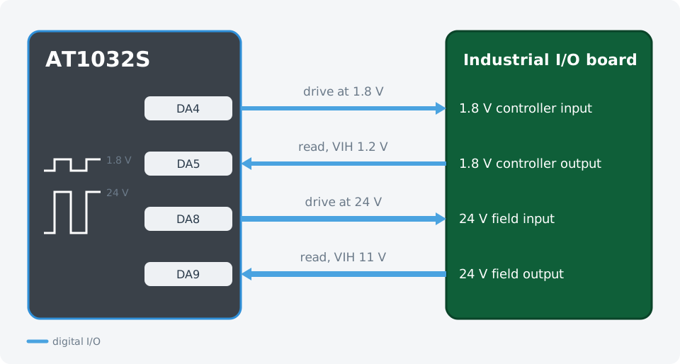
Four pins, two voltage worlds, one device. Each pin's levels are set in software.
Wiring
| AT1032S | Device under test | Levels |
|---|---|---|
DA4 | Controller input | output, 1.8 V logic |
DA5 | Controller output | input, 1.8 V thresholds |
DA8 | Field input | output, 24 V logic |
DA9 | Field output | input, 24 V thresholds |
The test sequence
- NodeJS
- Python
import { AT1000 } from '@ikalogic/at1000';

// ---- The two voltage domains on the board ---------------------------------
const LOW = {                       // 1.8 V controller side
  name: '1.8 V controller',
  out_io: 4, in_io: 5,
  voh: 1.8, vol: 0.0,               // what we drive
  vih: 1.2, vil: 0.6,               // how we read the board back
};
const HIGH = {                      // 24 V field side
  name: '24 V field I/O',
  out_io: 8, in_io: 9,
  voh: 24.0, vol: 0.0,
  vih: 11.0, vil: 5.0,
};
const PROPAGATION_MS = 50;          // time the board needs to react
// ---------------------------------------------------------------------------

const sleep = (ms) => new Promise((resolve) => setTimeout(resolve, ms));

const devices = await AT1000.findDevices();
const tester = await AT1000.open(devices[0]);
await tester.reset();

// Configure both domains up front. Each pin keeps its own levels.
for (const domain of [LOW, HIGH]) {
  await tester.gpio.digital(domain.out_io).configure_output({
    voh: domain.voh, vol: domain.vol,
    vih: domain.vih, vil: domain.vil,
    value: false,
  });
  await tester.gpio.digital(domain.in_io).configure_input({
    vih: domain.vih, vil: domain.vil,
  });
}

// Drive each level on the domain's output and confirm the board's output follows.
async function checkDomain(domain) {
  const driver = tester.gpio.digital(domain.out_io);
  const reader = tester.gpio.digital(domain.in_io);
  const results = [];

  for (const level of [false, true, false]) {
    await driver.write(level);
    await sleep(PROPAGATION_MS);
    const seen = await reader.read();
    const ok = seen === level;
    results.push(ok);
    console.log(
      `${domain.name}: drove ${level ? 'HIGH' : 'LOW '} ` +
      `at ${level ? domain.voh : domain.vol} V, ` +
      `read back ${seen ? 'HIGH' : 'LOW '} -> ${ok ? 'ok' : 'MISMATCH'}`);
  }

  await driver.write(false);
  return results.every(Boolean);
}

const lowOk = await checkDomain(LOW);
const highOk = await checkDomain(HIGH);

console.log('');
console.log(`1.8 V side: ${lowOk ? 'PASS' : 'FAIL'}`);
console.log(`24 V side:  ${highOk ? 'PASS' : 'FAIL'}`);

await tester.reset();
from ikalogic_at1000 import AT1000
import time

# ---- The two voltage domains on the board -----------------------------------
LOW = {                             # 1.8 V controller side
    "name": "1.8 V controller",
    "out_io": 4, "in_io": 5,
    "voh": 1.8, "vol": 0.0,         # what we drive
    "vih": 1.2, "vil": 0.6,         # how we read the board back
}
HIGH = {                            # 24 V field side
    "name": "24 V field I/O",
    "out_io": 8, "in_io": 9,
    "voh": 24.0, "vol": 0.0,
    "vih": 11.0, "vil": 5.0,
}
PROPAGATION_S = 0.05                # time the board needs to react
# -----------------------------------------------------------------------------

devices = AT1000.find_devices()
tester = AT1000.open(devices[0])
tester.reset()

# Configure both domains up front. Each pin keeps its own levels.
for domain in (LOW, HIGH):
    tester.gpio.digital(domain["out_io"]).configure_output(
        voh=domain["voh"], vol=domain["vol"],
        vih=domain["vih"], vil=domain["vil"],
        value=False,
    )
    tester.gpio.digital(domain["in_io"]).configure_input(
        vih=domain["vih"], vil=domain["vil"],
    )


def check_domain(domain):
    """Drive each level and confirm the board's output follows."""
    driver = tester.gpio.digital(domain["out_io"])
    reader = tester.gpio.digital(domain["in_io"])
    results = []

    for level in (False, True, False):
        driver.write(level)
        time.sleep(PROPAGATION_S)
        seen = reader.read()
        ok = seen == level
        results.append(ok)
        drove = domain["voh"] if level else domain["vol"]
        print(f"{domain['name']}: drove {'HIGH' if level else 'LOW '} at {drove} V, "
              f"read back {'HIGH' if seen else 'LOW '} -> {'ok' if ok else 'MISMATCH'}")

    driver.write(False)
    return all(results)


low_ok = check_domain(LOW)
high_ok = check_domain(HIGH)

print("")
print(f"1.8 V side: {'PASS' if low_ok else 'FAIL'}")
print(f"24 V side:  {'PASS' if high_ok else 'FAIL'}")

tester.reset()
tester.close()
Adapting it to your board
- Change
vohandvolto the levels your board expects to be driven with, andvihandvilto the thresholds that decide how its outputs are read. Outputs cover 0 to 24 V and input thresholds cover −25 V to +25 V. - Add a third domain the same way. Every pin is independent, so 5 V, 12 V and 3.3 V sections can all be driven from the same run.
PROPAGATION_MSis the settling time the board needs between the drive and the read.