I2C and SPI peripheral verification
The AT1032S has I2C and SPI masters built in, running at whatever logic voltage the board uses. So proving that every sensor, EEPROM and flash on an assembled board is present, correctly addressed and actually responding takes a script and a loom, with no dongles or adapters anywhere on the bench.
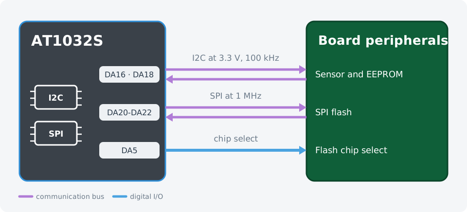
An I2C bus and an SPI bus, live at the same time, both at the board's own logic level.
Wiring
| AT1032S | Device under test |
|---|---|
DA16 SDA_0 | I2C data |
DA18 SCL_0 | I2C clock |
DA20 MOSI_1 | SPI flash data in |
DA21 MISO_1 | SPI flash data out |
DA22 SCK_1 | SPI flash clock |
DA5 | SPI flash chip select |
The test sequence
- NodeJS
- Python
import { AT1000 } from '@ikalogic/at1000';

// ---- The peripherals we expect to find ------------------------------------
const BUS_VCC = 3.3;                  // board logic voltage
const I2C_BAUD = 100000;

const SENSOR = { address: 0x68, id_register: 0x75, expected_id: 0x71, name: 'IMU' };
const EEPROM = { address: 0x50, page: 0x0010, name: 'EEPROM' };
const EEPROM_PAYLOAD = [0xA5, 0x5A, 0x12, 0x34];
const EEPROM_WRITE_MS = 10;           // page write cycle

const SPI_BAUD = 1000000;
const SPI_CS_IO = 5;
const FLASH_JEDEC_ID = 0x9F;          // read-identification opcode
const FLASH_EXPECTED = [0xEF, 0x40];  // first two bytes of the JEDEC id
// ---------------------------------------------------------------------------

const sleep = (ms) => new Promise((resolve) => setTimeout(resolve, ms));
const hex = (n) => '0x' + n.toString(16).padStart(2, '0').toUpperCase();

const devices = await AT1000.findDevices();
const tester = await AT1000.open(devices[0]);
await tester.reset();

const i2c = tester.com.i2c(0);
await i2c.enable({ vcc: BUS_VCC, baud_rate: I2C_BAUD });

// ---- 1. Scan the bus ------------------------------------------------------
// A device that acknowledges its address accepts a zero-length write.
const found = [];
for (let address = 0x08; address <= 0x77; address++) {
  try {
    await i2c.tx({ address, data: [], start: true, stop: true });
    found.push(address);
  } catch {
    // No acknowledge at this address: nothing is fitted there.
  }
}
console.log('I2C devices found:', found.map(hex).join(', ') || 'none');

// ---- 2. Identify a known device -------------------------------------------
await i2c.tx({
  address: SENSOR.address, data: [SENSOR.id_register], start: true, stop: false,
});
const [sensorId] = await i2c.rx({
  address: SENSOR.address, length: 1, start: true, stop: true, nack_last_byte: true,
});
const sensorOk = sensorId === SENSOR.expected_id;
console.log(`${SENSOR.name} id: ${hex(sensorId)} (expected ${hex(SENSOR.expected_id)}) ` +
            `-> ${sensorOk ? 'ok' : 'MISMATCH'}`);

// ---- 3. Write and read back an EEPROM page --------------------------------
const pageHigh = (EEPROM.page >> 8) & 0xFF;
const pageLow = EEPROM.page & 0xFF;

await i2c.tx({
  address: EEPROM.address,
  data: [pageHigh, pageLow, ...EEPROM_PAYLOAD],
  start: true, stop: true,
});
await sleep(EEPROM_WRITE_MS);

await i2c.tx({
  address: EEPROM.address, data: [pageHigh, pageLow], start: true, stop: false,
});
const readBack = await i2c.rx({
  address: EEPROM.address, length: EEPROM_PAYLOAD.length,
  start: true, stop: true, nack_last_byte: true,
});
const eepromOk = EEPROM_PAYLOAD.every((byte, i) => byte === readBack[i]);
console.log(`${EEPROM.name} read back: ${readBack.map(hex).join(' ')} ` +
            `-> ${eepromOk ? 'ok' : 'MISMATCH'}`);

await i2c.disable();

// ---- 4. Identify the SPI flash --------------------------------------------
const spi = tester.com.spi(1);
const cs = tester.gpio.digital(SPI_CS_IO);
await cs.configure_output({ voh: BUS_VCC, vol: 0, vih: 2.0, vil: 0.8, value: true });
await spi.configure({ vcc: BUS_VCC, baud_rate: SPI_BAUD, mode: 0, enabled: true });

// Chip select is an ordinary output, so the transaction boundary is yours to set.
await cs.write(false);
const flashId = await spi.trx([FLASH_JEDEC_ID, 0x00, 0x00, 0x00]);
await cs.write(true);

// The first byte is clocked out while the opcode goes in, so the id starts at byte 1.
const flashOk = FLASH_EXPECTED.every((byte, i) => byte === flashId[i + 1]);
console.log(`SPI flash id: ${flashId.slice(1).map(hex).join(' ')} ` +
            `-> ${flashOk ? 'ok' : 'MISMATCH'}`);

await spi.disable();

console.log('');
console.log(sensorOk && eepromOk && flashOk ? 'PASS' : 'FAIL');

await tester.reset();
from ikalogic_at1000 import AT1000
import time

# ---- The peripherals we expect to find ---------------------------------------
BUS_VCC = 3.3                      # board logic voltage
I2C_BAUD = 100000

SENSOR = {"address": 0x68, "id_register": 0x75, "expected_id": 0x71, "name": "IMU"}
EEPROM = {"address": 0x50, "page": 0x0010, "name": "EEPROM"}
EEPROM_PAYLOAD = [0xA5, 0x5A, 0x12, 0x34]
EEPROM_WRITE_S = 0.01              # page write cycle

SPI_BAUD = 1000000
SPI_CS_IO = 5
FLASH_JEDEC_ID = 0x9F              # read-identification opcode
FLASH_EXPECTED = [0xEF, 0x40]      # first two bytes of the JEDEC id
# -------------------------------------------------------------------------------

devices = AT1000.find_devices()
tester = AT1000.open(devices[0])
tester.reset()

i2c = tester.com.i2c(0)
i2c.enable(vcc=BUS_VCC, baud_rate=I2C_BAUD)

# ---- 1. Scan the bus ----------------------------------------------------------
# A device that acknowledges its address accepts a zero-length write.
found = []
for address in range(0x08, 0x78):
    try:
        i2c.tx({"address": address, "data": [], "start": True, "stop": True})
        found.append(address)
    except Exception:
        pass    # No acknowledge at this address: nothing is fitted there.

print("I2C devices found:", ", ".join(hex(a) for a in found) or "none")

# ---- 2. Identify a known device ----------------------------------------------
i2c.tx({"address": SENSOR["address"], "data": [SENSOR["id_register"]],
        "start": True, "stop": False})
sensor_id = i2c.rx({"address": SENSOR["address"], "length": 1,
                    "start": True, "stop": True, "nack_last_byte": True})[0]
sensor_ok = sensor_id == SENSOR["expected_id"]
print(f"{SENSOR['name']} id: {hex(sensor_id)} (expected {hex(SENSOR['expected_id'])}) "
      f"-> {'ok' if sensor_ok else 'MISMATCH'}")

# ---- 3. Write and read back an EEPROM page -----------------------------------
page_high = (EEPROM["page"] >> 8) & 0xFF
page_low = EEPROM["page"] & 0xFF

i2c.tx({"address": EEPROM["address"],
        "data": [page_high, page_low] + EEPROM_PAYLOAD,
        "start": True, "stop": True})
time.sleep(EEPROM_WRITE_S)

i2c.tx({"address": EEPROM["address"], "data": [page_high, page_low],
        "start": True, "stop": False})
read_back = i2c.rx({"address": EEPROM["address"], "length": len(EEPROM_PAYLOAD),
                    "start": True, "stop": True, "nack_last_byte": True})
eeprom_ok = list(read_back) == EEPROM_PAYLOAD
print(f"{EEPROM['name']} read back: {' '.join(hex(b) for b in read_back)} "
      f"-> {'ok' if eeprom_ok else 'MISMATCH'}")

i2c.disable()

# ---- 4. Identify the SPI flash ------------------------------------------------
spi = tester.com.spi(1)
cs = tester.gpio.digital(SPI_CS_IO)
cs.configure_output(voh=BUS_VCC, vol=0, vih=2.0, vil=0.8, value=True)
spi.configure(vcc=BUS_VCC, baud_rate=SPI_BAUD, mode=0, enabled=True)

# Chip select is an ordinary output, so the transaction boundary is yours to set.
cs.write(False)
flash_id = spi.trx([FLASH_JEDEC_ID, 0x00, 0x00, 0x00])
cs.write(True)

# The first byte is clocked out while the opcode goes in, so the id starts at byte 1.
flash_ok = list(flash_id[1:1 + len(FLASH_EXPECTED)]) == FLASH_EXPECTED
print(f"SPI flash id: {' '.join(hex(b) for b in flash_id[1:])} "
      f"-> {'ok' if flash_ok else 'MISMATCH'}")

spi.disable()

print("")
print("PASS" if sensor_ok and eeprom_ok and flash_ok else "FAIL")

tester.reset()
tester.close()
Adapting it to your board
BUS_VCCsets the bus voltage for both interfaces, so the same script covers a 1.8 V board and a 5 V board by changing one number.SENSORandEEPROMname the addresses and registers to check. Add an entry per device and loop over them.- I2C runs at 100 kHz, 400 kHz or 1 MHz; SPI runs up to 10 MHz in any of the four modes.
- A second I2C bus and a second SPI bus are available on the other pin group, so two independent board sections can be verified in one run.