Configuring the device
The Device card holds everything about how the instrument acquires: how fast it samples, for how long, and where the boundary between 0 and 1 sits. What it shows depends on the device, because the software builds the card from what the device reports it can do.
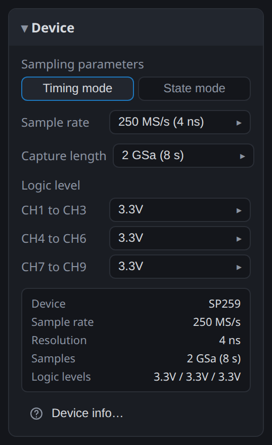
Sample rate and capture length
Sample rate is how often the device looks at the channels, and the figure beside it is the resolution that implies: 250 MS/s is one sample every 4 ns. A pulse shorter than one sample period may be missed entirely, and a pulse only one or two samples wide is measurable but not accurately. As a rule, sample at several times the fastest edge rate you care about.
Capture length is how many samples the device takes, with the duration that adds up to at the current rate. Changing the sample rate changes that duration, so the two are always set together: 2 GSa at 250 MS/s is 8 seconds, and the same 2 GSa at 25 MS/s is 80 seconds.
Both are lists rather than free values, because the device counts in fixed steps. The list runs from 1 MSa to 1 TSa in a 1-2-5 series on every model.
Timing mode and state mode
Timing mode is the normal one: the device samples on its own clock, at the rate you chose, and every sample is a point in time.
State mode samples on a clock taken from one of the channels instead. Each sample is then one beat of the system under test instead of a fixed interval. This is the mode to use on a synchronous bus: the capture holds one value per clock edge, however irregular that clock is, and the capture depth is spent on data instead of on the idle time between edges.
The clock channel is fixed by the hardware: CH9 on the SP259, and the ninth and eighteenth channel of each group on the SP1000G. You choose which edge of it to sample on. The SE254 has no state mode, so the toggle does not appear on it.
Logic levels
The threshold decides what counts as a 1. Set it to the signalling voltage of the bus, not to the supply of the board.
How finely you can set it differs by family:
- SE254: one threshold for all four channels, chosen from 1.8, 2.5, 3.3 and 5 V.
- SP259: three groups of three channels, each with its own threshold from the same list. This is what lets you watch a 3.3 V bus on CH1 to CH3 and a 5 V bus on CH4 to CH6 in one capture.
- SP1000G: a threshold per probe, set as a voltage anywhere from 0 to 3 V in 25 mV steps, with presets for 1.8, 3.3 and 5 V logic.
Probes, on the SP1000G
An SP1000G carries its channels on active probes. The card offers a threshold per probe rather than per group of channels, and there are no fixed logic levels:
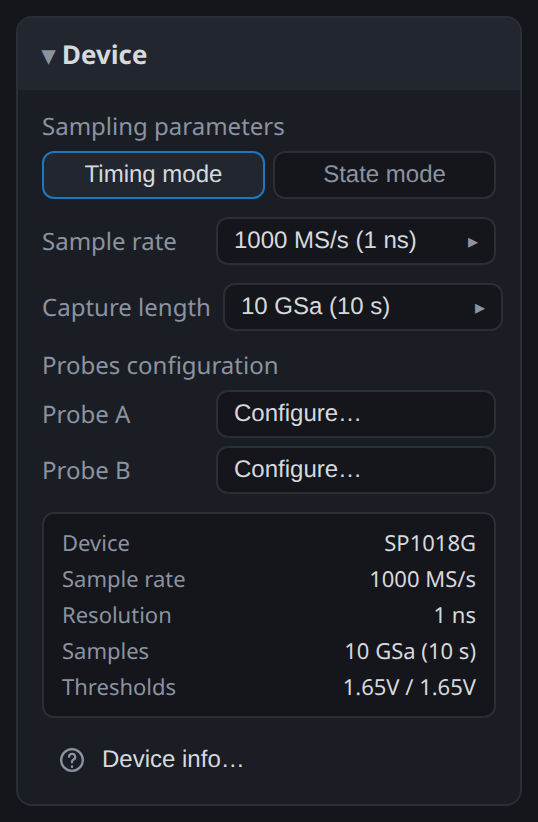
Configure… beside a probe opens its dialog:
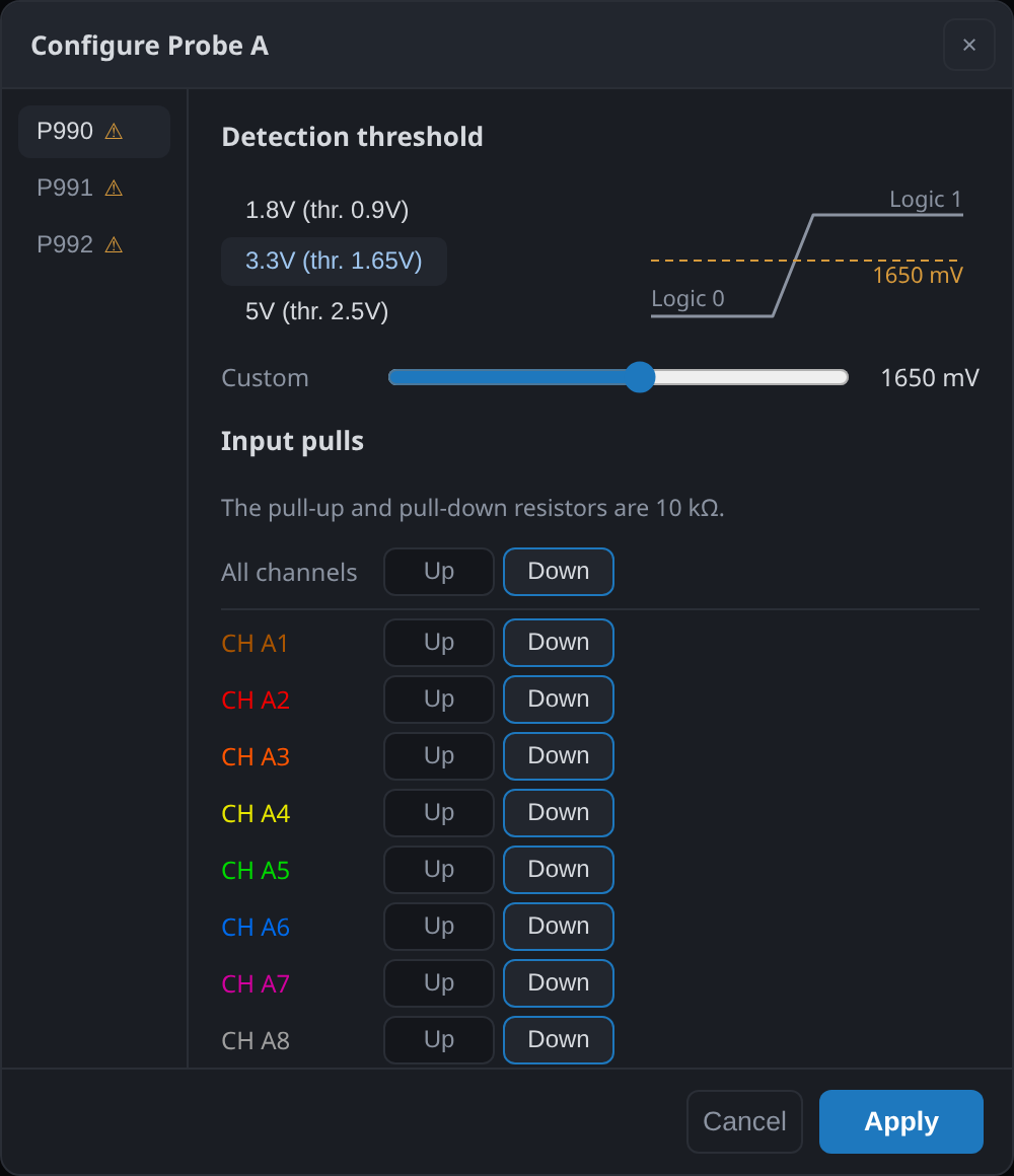
Detection threshold takes a preset or a value you set with the slider, shown in millivolts beside the diagram of where it falls between logic 0 and logic 1.
Input pulls switch a 10 kΩ pull-up or pull-down onto a channel, either for the whole probe at once or channel by channel. This matters on an open-drain bus, where a line with nothing driving it has no defined level, and on an unconnected input that would otherwise float and produce transitions that are not there.
Changes take effect on Apply.
Industrial inputs, on the SP259i
The SP259i has receivers for industrial buses beside its logic inputs, and Configure… beside "Industrial inputs" selects which ones are captured:
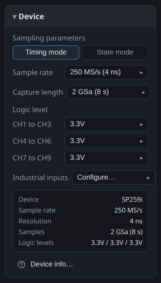
There are six: CAN bus, two RS485, two RS232 receive lines and LIN. They capture the bus itself not the logic either side of a transceiver. That is how you measure a transceiver: connect the industrial input to the bus and a logic channel to the transceiver's output, and the capture holds both, with the delay between them visible.
What the device is
The recap under the settings restates the configuration in one block. Check it before starting a long capture. Device info… opens what the instrument reports about itself: model, serial number, firmware version and temperatures.
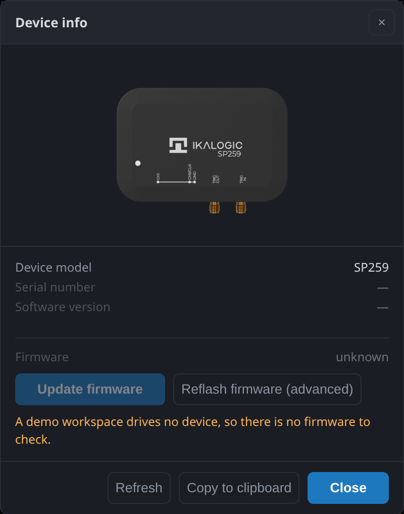
When a device needs newer firmware than it carries, ScanaStudio offers the update here rather than applying it silently.