Trigger
A trigger tells the instrument what to wait for. Without one the capture starts as soon as you press the button and stops when the memory is full. That works when the signal is always present, but not when it happens once an hour.
Everything about triggering is in the Trigger card:
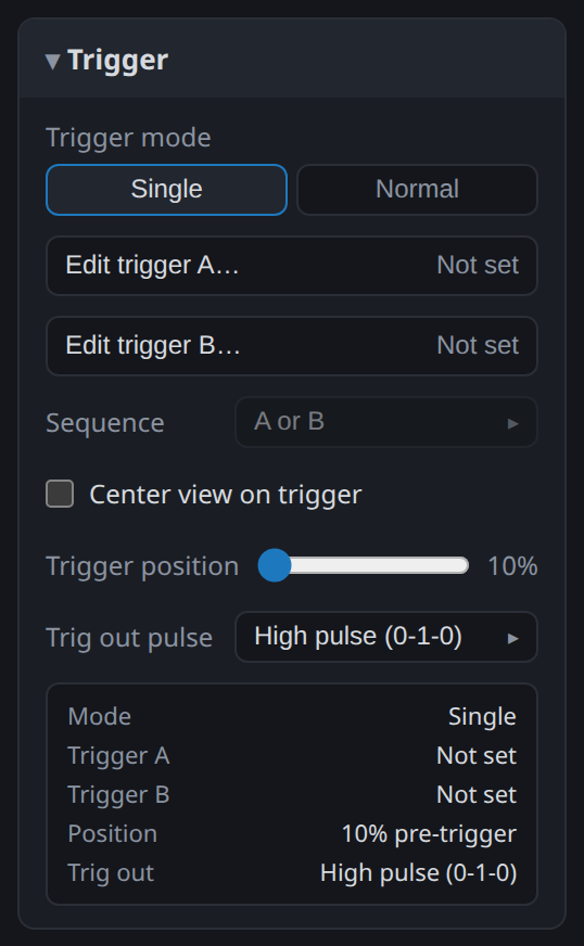
Trigger mode is Single or Normal. Single captures once and stops. Normal re-arms after each capture, so the device keeps waiting for the condition to happen again.
Edit trigger A… and Edit trigger B… open the editor. Sequence combines the two, and Trigger position decides how much of the capture is kept from before the event.
If you used ScanaStudio 3 or 5, the multi-step trigger was called the sequence trigger. In V6 it is Multistep trigger, and "sequence" now means something else: the order in which triggers A and B must happen.
Trigger conditions
The editor holds one condition. Which tabs it offers depends on the device.
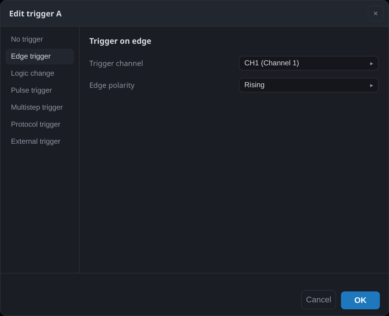
Edge
The simplest condition: a rising or a falling edge on one channel.
Logic change
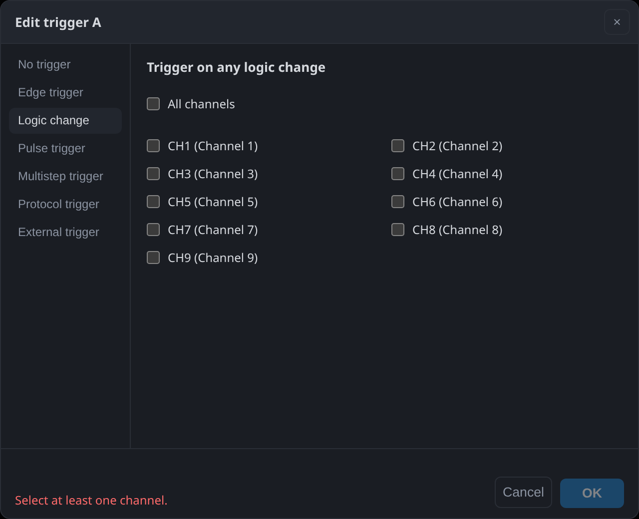
Fires on any change on any of the channels you select. It is the condition to reach for when you do not yet know what the board does: arm it on everything, capture, and look at what moved.
Pulse
Fires on a high pulse (0-1-0) or a low pulse (1-0-1) whose width falls inside a range you give. It catches a glitch too short to be legitimate, or a strobe that has grown too long.
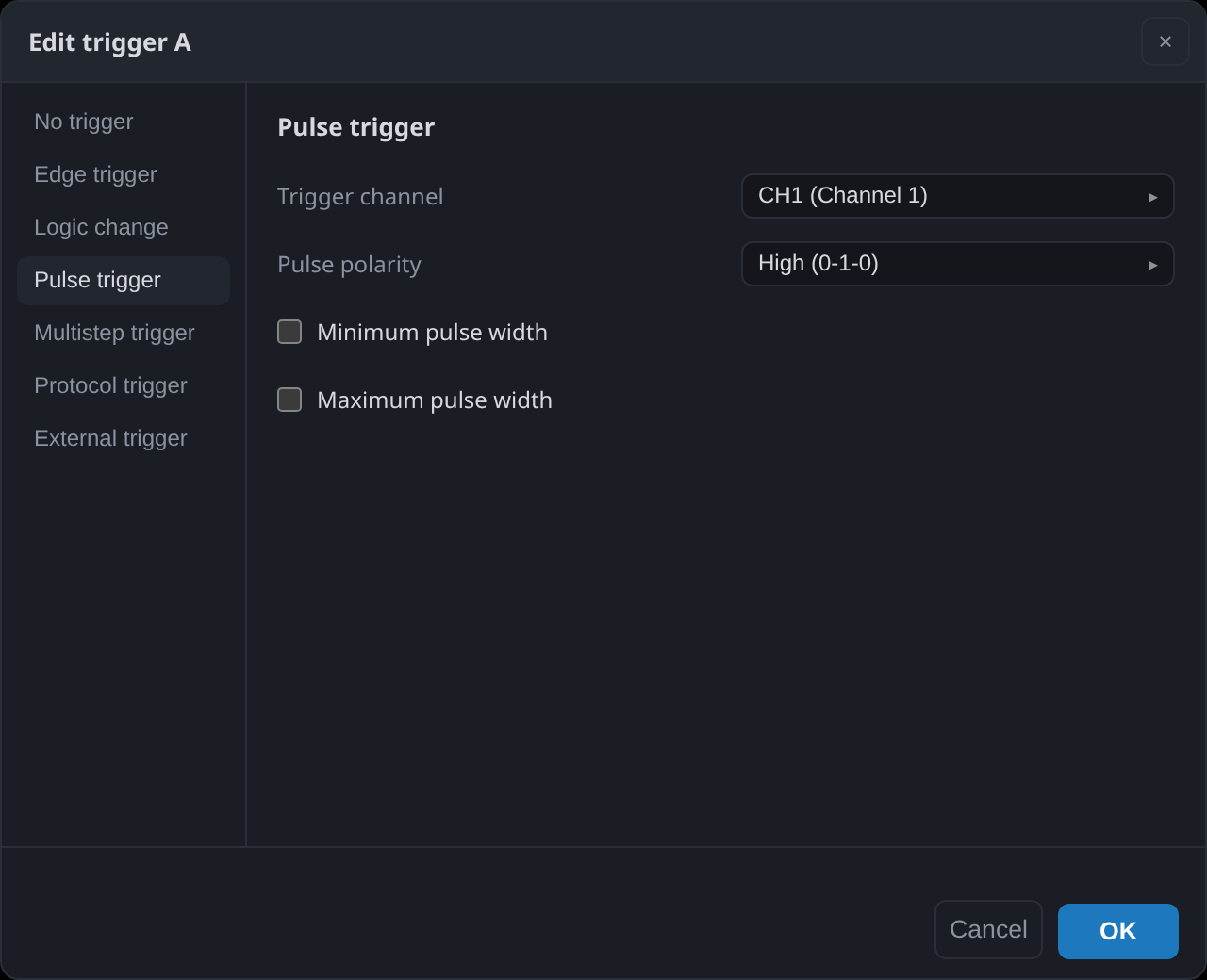
The editor shows the width it will actually use beside the one you typed. The device measures width by counting its own clock, so the achievable value is a whole number of those periods and your figure is rounded to the nearest one. The difference matters when the width you are hunting is only a few clock periods long.
Multistep
A sequence of steps, each describing the state of one or more channels, that must occur in order. This is how you trigger on something a single edge cannot describe: an address on a parallel bus, a chip select that falls only while a clock is already running, a start condition followed by a particular byte.
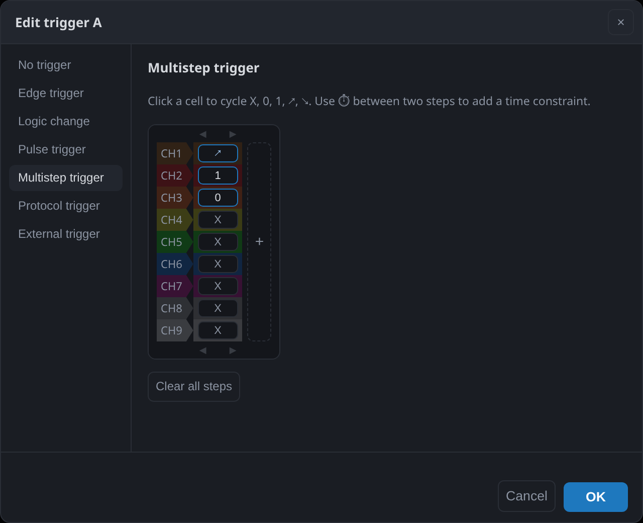
Click a cell to cycle it through the states: X ignore, 0 low, 1 high, ↗ rising edge and
↘ falling edge. + adds a step, and the clock icon between two steps adds a time
constraint, so a step must follow the previous one within, or no sooner than, a delay you give.
A step must contain something other than X, and it may contain at most one edge: a step is one
instant, and two edges at the same instant on different channels is not a condition the device
can wait for. Use two steps for that.
External
Fires on a signal fed to the TRIG IN connector, rising or falling. It is how another instrument starts this one.
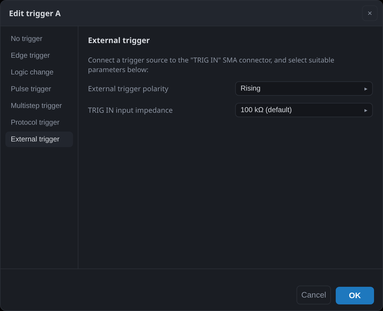
The SE254 has no TRIG IN, so the tab does not appear on it.
Combining A and B
A device with two trigger engines can hold two conditions at once and combine them:
| Sequence | Fires when |
|---|---|
| A then B | B happens, and A happened before it |
| B then A | A happens, and B happened before it |
| A or B | either one happens |
| A and B | both have happened, in either order |
| A and B (any order) | both have happened, in either order |
A single condition often fires too often. A falling edge on chip select happens constantly, while "a 10 ms pulse on CH1, then a falling edge on CH2" happens only in the case you are looking for.
The SE254, SP259 and SP1018G have two engines. The SP1036G and SP1054G report one, because on those models only engine A is wired to the bus that carries trigger status between channel groups, so A/B sequences are not available on them.
Trigger position
The trigger is not necessarily at the start of the capture. Trigger position sets how much of the acquisition is spent on what happened before it:

At 10 %, a tenth of the capture is pre-trigger and the rest is what followed. At 75 %, three quarters of it is what led up to the event. Which you want depends on whether the trigger is the start of the story or the end of it: for a fault, the interesting part is almost always what came before.
The device cannot always deliver what you ask for. Pre-trigger samples have to already be in memory when the condition fires, so a trigger that fires immediately after the capture starts leaves the device with less history than you requested. It captures what it has and fills the rest afterwards, rather than failing. The SP259 holds up to 650 MSa of pre-trigger; the SE254 uses a ring buffer of about 2.7 GSa.
Center view on trigger in the Trigger card puts the trigger instant in the middle of the window when the capture lands, which saves hunting for it.
Trigger output
The SP259 and the SP1000G series drive a pulse on TRIG OUT when the trigger fires, which starts an oscilloscope or another analyzer at the same instant. The output is always active; the setting chooses its polarity.
After the capture
The trigger instant is marked on the waveform by a marker you cannot move or delete, so you can
always find it, and Ctrl+T jumps to it.