SP259 and SP259i
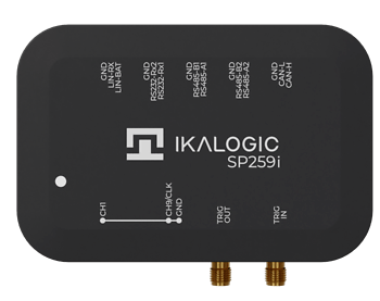
The SP259 series captures 9 channels at 250 MS/s, a resolution of 4 ns. Nine channels is eight bits of a parallel bus plus a clock or strobe.
There are two devices. Both have the same nine logic inputs; the SP259i adds industrial receivers for CAN, LIN, RS232 and RS485.
Principle of operation
A USB logic analyzer normally works one of two ways. It either stores samples in an embedded memory and downloads them afterwards, which is not limited by the USB transfer rate but is limited by the size of that memory; or it streams samples over USB as they are taken, which gives virtually unlimited depth but caps the sampling rate at the throughput of the link.
The SP259 does both. A 1 Gb HyperRAM stores compressed samples at 4 Gb/s while the USB 3 interface transfers them out at the same time, emptying the memory and making room for more. It records dozens of minutes of activity on all nine channels at 250 MS/s.

What it can be asked to do
| Channels | 9 |
| Maximum sample rate | 250 MS/s, 4 ns |
| Logic levels | 1.8 V, 2.5 V, 3.3 V, 5 V |
| Threshold groups | 3: CH1 to CH3, CH4 to CH6, CH7 to CH9 |
| State mode clock | CH9 |
| Trigger engines | 2, so A/B sequences are available |
| Pre-trigger | up to 650 MSa |
| External trigger in and out | yes, SMA |
| Industrial inputs | SP259i only: CAN, RS485 x2, RS232 Rx x2, LIN |
| Pattern generator | no |
Three independent thresholds are the feature that most often decides a measurement: a board with a 3.3 V microcontroller talking to a 5 V peripheral can be captured in one go, with CH1 to CH3 set for one and CH4 to CH6 for the other.
Detailed timing and DC characteristics are in the SP259 series datasheet.
Typical applications
- Embedded systems debugging
- Research and education
- Serial protocol analysis: I2C, SPI, UART, 1-Wire and others
- Industrial bus analysis: RS232, RS485, CAN, LIN
- ADC diagnostics
The SP259i can capture an industrial bus and the logic either side of a transceiver at the same time. That is how you measure the delay through it, or catch it failing intermittently.
Device ports
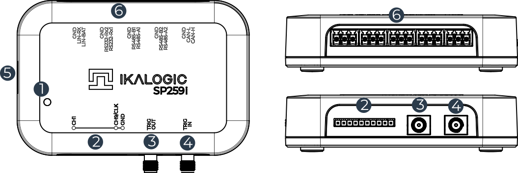
- Status LED
- 9-channel logic probe input
- Trigger OUT, SMA
- Trigger IN, SMA
- USB port
- Industrial port, SP259i only
What is in the box
-
1 m USB 3.0 cable, micro-B to A

-
10 logic probes: 9 signals and 1 ground

-
5 pluggable terminal blocks, SP259i only (Würth 691361100003 or equivalent)

-
Two SMA anti-dust covers

Drivers
The SP259 carries an FTDI FT601 for its USB 3 interface, which needs FTDI's D3XX driver.
ScanaStudio V6 does not bundle drivers. Install the Ikalogic USB driver package once, before connecting the device: ikalogic-drivers-setup.exe. It is the only Ikalogic installer that needs administrator rights; ScanaStudio itself installs per-user and never prompts for UAC.
If the device still shows a warning in the device manager afterwards, install the D3XX driver package by hand: unzip it to a known folder, connect the SP259 directly to a root USB 3 port rather than through a hub, find it in the device manager, choose "Update driver" and point the wizard at that folder.
On Linux, the udev rule shipped with ScanaStudio is what allows the software to open the device. See Installing ScanaStudio.
LED indications
| LED state | Meaning |
|---|---|
| Off | Not powered, or not connected to a USB port |
| Orange | Connected to USB, not yet configured |
| White | Connected and configured |
| White blinking | Logic activity detected on one or more channels |