SP1000G series
The SP1000G series captures 18 to 54 channels at 1 GS/s, a resolution of 1 ns, on every channel at once. Channels can also be driven, so the same instrument stimulates a board and records the response in one capture.
A device is made of two parts. The host holds the acquisition hardware: FPGA, memory buffer and USB interfaces. The active probes hold the signal conditioning, ESD protection, input/output buffers and level shifting. Each probe connects to the host through a harness of high-speed Twinax cables, so the propagation delay is predictable and the channels stay aligned with one another.
External reference clock in and out, trigger in and out, an adjustable threshold and a settable output voltage make it the instrument in the range for work where timing has to be defensible.
The three models
| SP1018G | SP1036G | SP1054G | |
|---|---|---|---|
| Channels | 18 | 36 | 54 |
| Active probes | 2 | 4 | 6 |
| Sample rate | 1 GS/s on all channels | same | same |
| Trigger engines | 2 | 1 | 1 |
They share an architecture and differ in how many probes attach. On the SP1036G and SP1054G only engine A is wired to the bus that carries trigger status between channel groups, so those two report a single trigger engine and the A/B sequences described in Trigger are not available on them.
What it can be asked to do
| Maximum sample rate | 1 GS/s, 1 ns |
| Threshold | set per probe, 0 to 3 V in 25 mV steps |
| Threshold presets | 1.8 V, 3.3 V, 5 V logic |
| Channel pull-up / pull-down | yes, 10 kΩ, per channel or per probe |
| State mode clock | the 9th and 18th channel of each group |
| External trigger in and out | yes |
| Reference clock in and out | yes, 10 MHz |
| Pattern generator | yes, one script at a time |
| Maximum output rate | 125 MHz |
Channels are individually configurable as inputs, push-pull outputs or open-drain outputs. See Configuring the device for the probe dialog, and Pattern generator for driving them.
Detailed timing and DC characteristics are in the SP1000G series datasheet.
Memory and streaming
A USB logic analyzer normally either stores samples in an embedded memory and downloads them afterwards, which is bounded by that memory, or streams them as they are taken, which is bounded by the USB throughput.
The SP1000G does both, and compresses. Samples are analyzed and compressed before being stored in an embedded DDR-3 memory of 4, 8 or 12 Gb depending on the model, while a USB 3 interface transfers them out at the same time, emptying the memory and making room for more. The result is hours of activity on all channels at 1 GS/s, without the host computer or the USB link setting the limit.
Typical applications
- Semiconductor testing, manual or automated
- Circuit testing and validation
- Embedded systems debugging
- Scientific research
- Serial protocol analysis: I2C, SPI, UART, 1-Wire and others
- ADC diagnostics
Device ports
Host
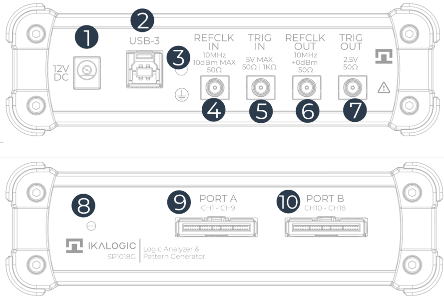
- 12 V DC power input
- USB 3 port, type B
- Earth connection, M3 thread
- 10 MHz reference clock input, 50 Ω, optional
- Trigger input, 50 Ω
- Reference clock output
- Trigger output
- Status LED
- Port A, for a 9-channel active probe set
- Port B, for a 9-channel active probe set
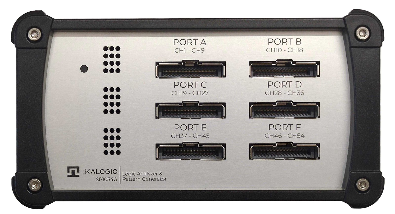
A model with more probes has more ports. Below is the front of an SP1054G, with its six:
Active probe
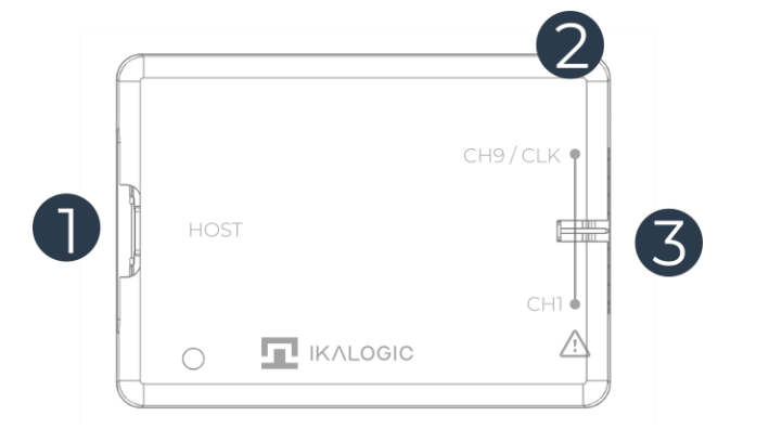
- Connection to the host
- Status LED
- Connection to the device under test: 9 measurement channels, each with its own ground
What is in the box
Every model ships with the host device, a 12 V 3 A power supply and a 1.5 m USB 3 cable, type A to B, plus one active probe and one harness per nine channels: two for the SP1018G, four for the SP1036G, six for the SP1054G.
Drivers
ScanaStudio V6 does not bundle drivers. Install the Ikalogic USB driver package once, before connecting the device: ikalogic-drivers-setup.exe. It is the only Ikalogic installer that needs administrator rights; ScanaStudio itself installs per-user and never prompts for UAC.
The SP1000G Core devices, one per group of 18 channels, use FTDI's D3XX driver. If a Core device still shows a warning in the device manager after installing the package, install D3XX by hand: unzip it to a known folder, connect the device directly to a root USB 3 port rather than through a hub, find it in the device manager, choose "Update driver" and point the wizard at that folder. Until the driver is installed Windows cannot enumerate it properly, so it may be listed as "IKALOGIC Device", "IKALOGIC COM PORT" or "USB Serial port", usually with a yellow exclamation mark.
On Linux, the udev rule shipped with ScanaStudio is what allows the software to open the device. See Installing ScanaStudio.
LED indications
Host
| Status LED | Meaning |
|---|---|
| Red, steady | Booting, for about 15 seconds after power-up |
| Green, steady | Ready |
| Fuchsia | Waiting for the trigger |
| Blue, blinking | Capturing |
| Red, blinking | Hardware fault |
Active probe
| Status LED | Meaning |
|---|---|
| Green, steady | Probe powered |
| Green, blinking | Logic activity on one or more channels |
| Red, blinking | Hardware fault |
Auto-test
The SP1000G can test itself, because it can generate as well as capture. The procedure needs no other equipment: the device and one probe set.
Leave the probes floating during the auto-test. They must not be connected to anything else.
The test generates a known pattern on all channels of a probe and captures it back. The pattern uses a range of pulse widths so timing accuracy is exercised, and odd channels carry the inverse of even channels, so a short between two channels is immediately visible.

- Connect the device to USB 3 and to its power supply.
- Start ScanaStudio and open an SP1000G workspace, keeping the default settings.
- Connect one probe set to the port under test, for example Port A.
- In the Pattern Generator card, Add script, and choose Auto-test SP1000G. If it is not in the list, install it from the script manager.
- Start the capture. The device generates and captures at the same time.
- Compare what you get with the pattern above.
First capture
The general procedure is in Your first capture. Two things are specific to this device: connect the power supply as well as USB 3, and connect at least one ground probe to the ground of the system under test.