Pattern generator
The SP1000G series can drive its channels as well as read them, so it can stimulate a board and record the response in the same capture. The SE254 and the SP259 have no outputs, so the Pattern Generator card does not appear on them.
A pattern is produced by a generator script: you add one to the workspace, configure it, and start. ScanaStudio runs the script, sends the resulting pattern to the device, and the device generates it while capturing.
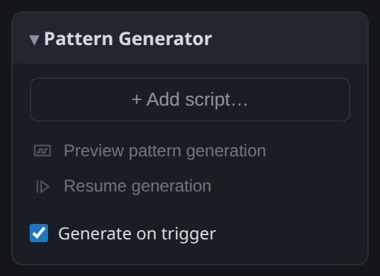
Adding a generator
Add script lists the generator scripts in the library:
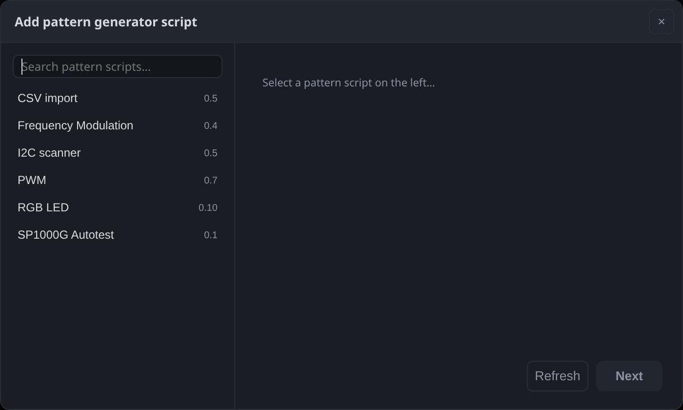
Pick one, click Next, fill in its form and click Add. The row that appears carries the script name, the channel it drives, and whether it is armed:
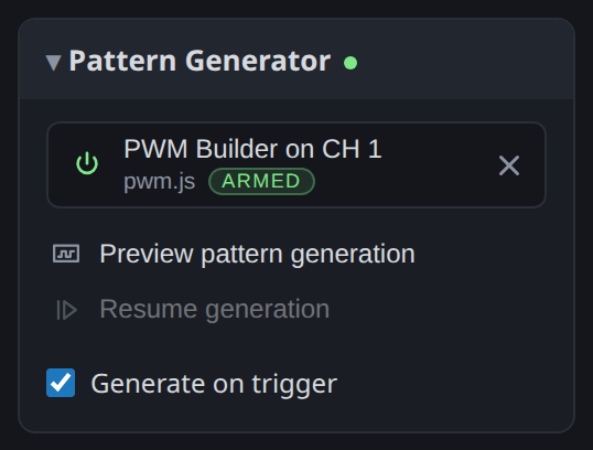
The switch on the left stops generating without removing the script; the cross removes the script and its settings. There is one generator script per workspace, so Add script is disabled once one is present.
Preview pattern generation interprets the script without touching the hardware, which is the quick way to check that a pattern is what you meant before driving it onto a board.
Generate on trigger holds the pattern until the trigger condition fires, instead of starting it with the capture.
Starting the capture generates and captures together, so the pattern comes back on the channels that recorded it, provided the probes are floating or connected to high-impedance inputs.
The scripts that ship
CSV importer
Builds a signal from a CSV file. Use it to replay a pattern captured elsewhere, or produced by another tool.
A column is a channel, and there are two ways to lay the file out.
One or more transitions per line, with a time column: each line says how long the levels on that line last. Only transitions are stored, so the file stays small even for a long pattern.

One sample per line, with no time column: every line is one sample period, and you give that period in the script's options.

The form asks for, in order: the file; whether to skip the first line as a header; which of the two structures it uses, with the time column index or the sampling period; which column drives which channel; the column separator and the decimal separator; and the electrical settings, namely output voltage in millivolts, the idle state held when nothing is generated, and whether the outputs are push-pull or open-drain.
Two common mistakes: column numbering starts at 0, and the time column must not also be mapped to a channel.
I2C scanner
Generates a call to every I2C address in turn so you can see which ones a device answers. Add an I2C decoder on the same two channels and the answers are decoded as they come back, which turns the capture into a list of the devices present on the bus.
Give it the SDA and SCL channels and a clock frequency. Keep that frequency well below the sampling rate, or the capture will not resolve the bus it is generating.
PWM
Generates a PWM signal on one channel, either at a fixed duty cycle or with the duty cycle modulated by a sine, triangle or sawtooth.
For a fixed duty cycle: the carrier frequency, the duty cycle as a percentage, and the number of cycles to generate. For a modulated one: the modulation shape, its frequency and phase, the carrier frequency and the number of cycles. The carrier must be higher than the modulation frequency, and the shortest pulse is bounded by the device's maximum output rate of 125 MHz.
Switching on the decoder's duty cycle graphic plots the result as a curve, which is the clearest way to check a modulated pattern: see Plotting decoded data.
Frequency modulation
The same idea applied to frequency rather than width: a square wave at a fixed 50 % duty cycle whose frequency is either constant or modulated by a sine, triangle or sawtooth. The options mirror the PWM script's.
RGB LED
Generates the single-wire protocol used by addressable LED strips, for testing a driver without the strip.
SP1000G auto-test
Generates a known pattern on every channel of a probe so you can verify the device itself. See the SP1000G page for the procedure.
Writing your own
A generator is a JavaScript file that implements on_pattern_generate. If none of the above
produces what you need, the
pattern generator scripting chapter covers
writing one, and a script can also be driven from the
SDK.